Constraint-driven PROTAC design treats degrader construction as a geometry-aware assembly problem. A candidate
PROTAC must not only contain a protein-of-interest warhead, linker, and E3 recruiter; it must connect two bound
ligands through attachment atoms that can plausibly support a ternary complex.
In practice, that means a PROTAC is physically constrained by its two bound ligands, the linker must bridge real
exit vectors, and the target plus E3 ligase must adopt an orientation that can exist without impossible strain or
buried linker paths. Structure-first preparation helps remove implausible candidates before synthesis or heavier
ternary-complex modeling.
Anchor-aware designBridgeability firstStructure-grounded assemblyValidation still required
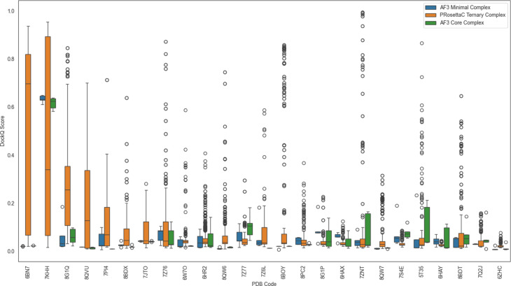
Figure 1. Benchmark overview: model-quality distributions varied strongly across systems, with
constraint-guided PRosettaC and unconstrained AF3 behaving differently across the 36-system reference set.
Figure from Schulz et al., Scientific Reports (2025),
doi:10.1038/s41598-025-21502-8,
displayed unmodified under CC BY-NC-ND 4.0.
Figure 1. This larger top-of-page view gives the benchmark overview enough room for readers to
inspect the score distributions before moving into the interpretation sections below.
Quick answer: what is constraint-driven PROTAC design?
Constraint-driven PROTAC design is a workflow that uses known or modeled binding poses, defined anchor atoms, linker
length and shape constraints, and candidate protein-protein orientations to decide whether a warhead-linker-recruiter
design is geometrically plausible before downstream modeling or experimental testing.
Start from a POI ligand bound to the target and an E3 recruiter bound to the ligase.
Identify solvent-exposed anchor atoms or exit vectors on both ligands.
Estimate whether a linker can bridge the two anchors without disrupting binding.
Enumerate linkers with varied length, rigidity, and chemistry.
Export plausible candidates into ternary-complex modeling.
Evaluate interface geometry, linker strain, solvent exposure, and ensemble behavior.
Validate experimentally with degradation assays.
Why PROTAC design is a geometry problem
PROTACs work by induced proximity, so the degrader must position the target protein and E3 ligase in a productive
orientation. Binary binding alone is insufficient. The linker does not merely connect two fragments; it imposes
distance, orientation, flexibility, and strain constraints on the whole ternary hypothesis.
A candidate can look valid in 2D and still fail in 3D because the linker cannot bridge the bound poses.
Even good binders can fail if one exit vector points into buried protein volume or away from the partner protein.
Productive degradation depends on a target-E3 arrangement that the physical degrader can actually occupy.
Builder positioning: PROTAC Builder is a preparation layer. It helps users define components,
anchors, and assembled candidates, then hand them off to downstream modeling. It does not guarantee ternary-complex
formation or degradation.
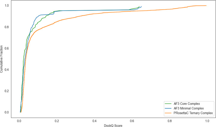
Figure 2. Cumulative DockQ distributions highlight why degrader-specific methods are judged by
how often they reach useful high-scoring tails, not just by average-looking protein-complex poses.
Figure from Schulz et al., Scientific Reports (2025),
source article,
displayed unmodified under CC BY-NC-ND 4.0.
These are the atoms where the linker attaches to the POI ligand and the E3 recruiter. They should usually be solvent-exposed and avoid key binding contacts.
Exit-vector direction
The direction the linker leaves each bound ligand strongly affects whether the bridge points toward the partner protein or into empty or buried space.
Distance and reach
The end-to-end span between anchors sets a reach problem. Too short causes clashes or impossible geometry; too long raises entropy and often weakens cooperativity.
Linker flexibility and strain
Flexible linkers sample more conformations but pay entropic cost. Rigid linkers can preserve geometry but fail quickly when the vectors are wrong.
Protein-protein orientation
The target and E3 ligase still need an arrangement compatible with the selected linker, anchor chemistry, and recruited binding modes.
Interface quality
Productive complexes often rely on favorable protein-protein contacts, solvent exposure, and accessible ubiquitination geometry rather than ligand binding alone.
Linker bridgeability: a bridgeable PROTAC is one whose linker can connect the two chosen anchors
across a plausible target-E3 orientation without impossible strain, clashes, or buried paths through protein volume.
Start from solved structures when possible
Constraint-driven design is strongest when grounded in experimentally resolved structures: a POI-ligand complex, an
E3-recruiter complex, and ideally a known PROTAC ternary complex when one exists for a related system. Solved
structures define the ligand binding mode, exit vector, pocket geometry, exposed atoms, and likely steric clashes.
Use modeled structures carefully when no solved structure is available, and document that uncertainty.
Anchor selection is only as good as the binding pose used to define it.
Constraint-driven assembly becomes much weaker if one or both ligand poses are speculative.
POI Side
Warhead Discovery
Start from target-binding ligands with plausible exit vectors and structure support.
The Scientific Reports benchmark compared two modeling philosophies on 36 crystallographically resolved PROTAC
ternary complexes: broad, general protein-complex prediction with AlphaFold3 and PROTAC-specific,
Rosetta-based, anchor-constrained modeling with PRosettaC.
AlphaFold3
Fast and general for protein-complex prediction, but it does not explicitly enforce degrader-specific linker geometry or anchor constraints.
PRosettaC
Uses known warhead and recruiter poses plus chemically defined anchors, so it can generate more degrader-relevant ternary poses when those constraints are compatible.
PRosettaC produced successful models for 25 of 36 benchmarked systems and failed in 11.
It was the top-performing method in 48% of modeled cases, but not universally.
AF3 full-complex scores could be inflated by accessory proteins such as Elongin B/C or DDB1.
PRosettaC often showed a longer high-scoring DockQ tail, but it was brittle when anchors or linker sampling were wrong.
Practical takeaway: the benchmark supports constraint-guided modeling as a useful strategy for
geometry-aware PROTAC design when reliable anchors and binding modes are available. It does not mean PRosettaC
always wins, and it does not remove the need for experimental validation.
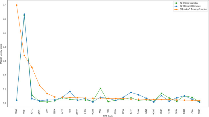
Figure 6. Median DockQ by system shows why no single method dominates every case. PRosettaC is
strong in some systems, but not universal, which reinforces the need for method-aware interpretation.
Figure from Schulz et al., Scientific Reports (2025),
doi link,
displayed unmodified under CC BY-NC-ND 4.0.
Figure 1. Median-centered DockQ distributions show broad variability across systems and methods;
PRosettaC reaches higher medians in some targets but not all. Figure from Schulz et al., displayed unmodified under CC BY-NC-ND 4.0.
Figure 2. Cumulative DockQ curves emphasize tail behavior; PRosettaC accesses more high-scoring
outliers in favorable systems, which matters for ternary-complex prioritization. Figure from Schulz et al., displayed unmodified under CC BY-NC-ND 4.0.
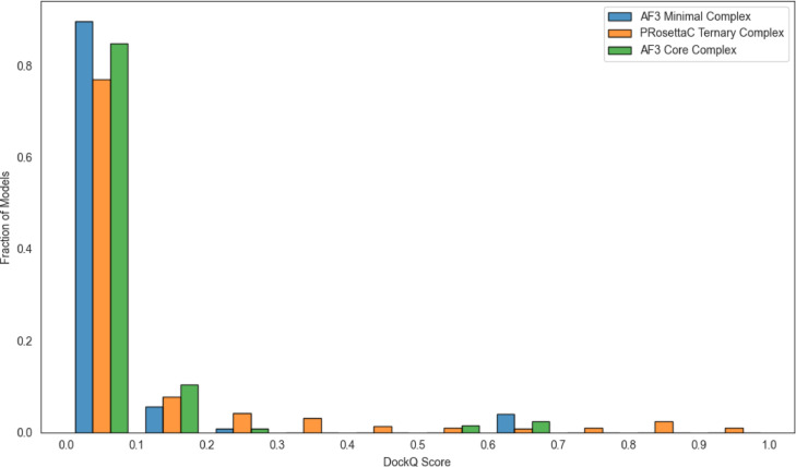
Figure 3. Normalized DockQ distributions show that most sampled models remain low-scoring, while
constraint-guided methods can access more mid- and high-quality bins when the geometry is compatible. Figure from Schulz et al., displayed unmodified under CC BY-NC-ND 4.0.
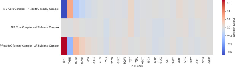
Figure 4. Median DockQ difference heat maps make the method-to-method tradeoffs explicit rather
than collapsing them into one summary score. Figure from Schulz et al., displayed unmodified under CC BY-NC-ND 4.0.
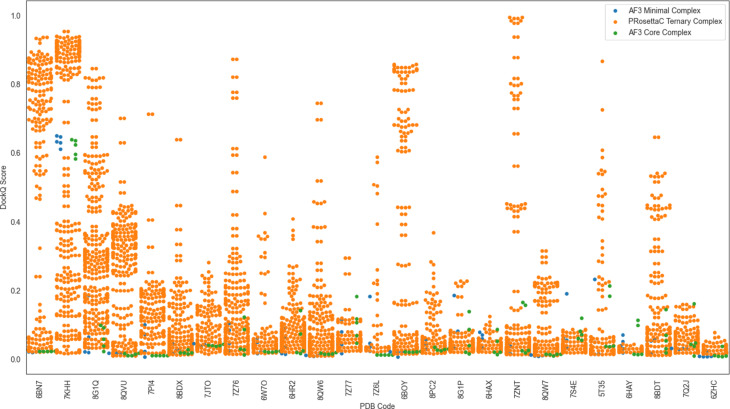
Figure 5. Swarm-plot variability shows how PRosettaC can generate many sampled poses, including
high-scoring outliers, even when median performance is modest. Figure from Schulz et al., displayed unmodified under CC BY-NC-ND 4.0.
Figure 6. Per-system medians reinforce that PRosettaC is often strong in favorable systems but
does not universally dominate every target-E3 pair. Figure from Schulz et al., displayed unmodified under CC BY-NC-ND 4.0.
PRosettaC-style logic starts from known warhead and recruiter binding poses, defines anchor atoms on each ligand, and
models the PROTAC linker as a physical bridge between those anchors. Candidate protein orientations are sampled under
the constraint that the linker must actually connect the two bound ligands.
This filters out many geometrically impossible protein poses before downstream ranking.
It keeps the ternary-complex question tied to the actual degrader chemistry instead of a protein-only complex fantasy.
It makes the modeling assumptions explicit and testable.
Caution: bad anchors produce bad constraints. If the chosen attachment atom is buried, disrupts
binding, or points away from the partner protein, a constraint-driven model can fail or become misleading.
AlphaFold3 limitations for PROTAC ternary complexes
AlphaFold3 is powerful for many biomolecular structure-prediction tasks, but PROTAC ternary complexes are unusual
because the small-molecule linker imposes explicit chemical constraints. A globally plausible protein-protein
arrangement may still be impossible for a specific degrader.
AF3 can place the target and ligase in orientations that look reasonable yet cannot be bridged by the actual linker.
Accessory proteins can inflate full-complex scoring even when the degrader-relevant target-E3 interface is weak.
Scaffold-stripped or interface-focused evaluation is more informative for PROTAC interpretation than global confidence alone.
Practical takeaway: for PROTAC modeling, evaluate the interface that matters: the target-E3
geometry made possible by the actual degrader, not only the global protein assembly.
Figure 4. The benchmark’s comparison heat map is a good reminder that method differences are
system-specific and should be interpreted at the degrader-relevant interface level. Figure from Schulz et al.,
displayed unmodified under CC BY-NC-ND 4.0.
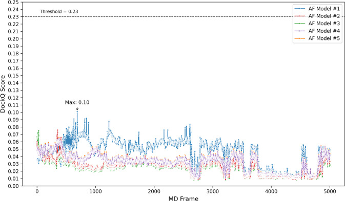
Crystal structures are snapshots, while ternary complexes are dynamic. A predicted pose may look poor against one
static crystal frame and still align with a transient conformation sampled along an MD trajectory. The benchmark
introduced frame-by-frame DockQ evaluation to expose that hidden compatibility.
Figure 7. AF3 minimal predictions in the benchmark stayed low-scoring across the dynamic
reference ensemble, showing that a static pose can remain incompatible even after local conformational motion.
Figure from Schulz et al., displayed unmodified under CC BY-NC-ND 4.0.
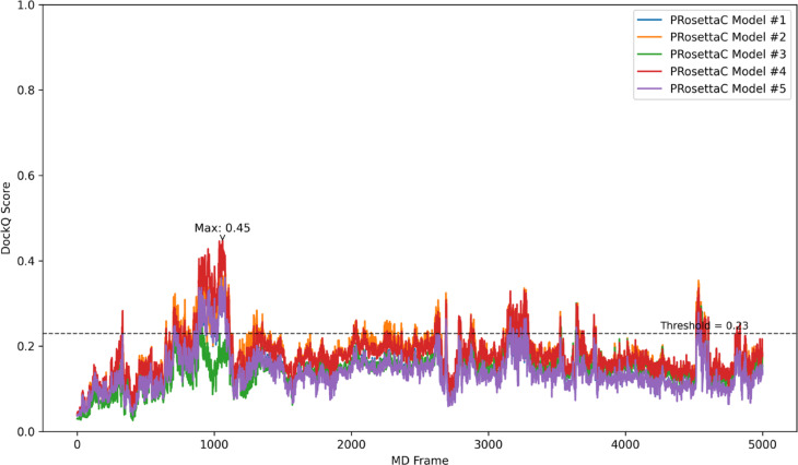
Figure 8. Several PRosettaC predictions transiently improved against MD frames, revealing
compatibility that a single static crystal comparison would miss. Figure from Schulz et al., displayed unmodified under CC BY-NC-ND 4.0.
Ensemble thinking: MD is not required for every early design, but dynamic evaluation can help when
a candidate looks borderline, when multiple poses compete, or when one static structure seems too restrictive.
A practical constraint-driven workflow for PROTAC Builder
Select the POI context: define the target, isoform, domain, and biological rationale.
Select or import a POI warhead: prefer known binding modes or solved structures and confirm a plausible exit vector.
Select an E3 recruiter: use E3 Ligandalyzer when possible and inspect binding pose, solvent exposure, and attachment atom.
Define anchor atoms explicitly on both the warhead and recruiter sides.
Build a linker panel that varies length, rigidity, polarity, and chemistry around a geometric hypothesis.
Check bridgeability: ask whether the linker can physically connect anchors across plausible protein orientations.
Generate candidate PROTACs in PROTAC Builder for standardized assembly and representation.
Export to downstream modeling with PRosettaC-style or other constraint-aware workflows when compatible.
Score and filter using linker strain, interface quality, solvent exposure, clashes, and ensemble behavior.
Validate experimentally with degradation, DC50, Dmax, selectivity, and hook-effect readouts.
Benefits of constraint-driven design
Reduces arbitrary linker enumeration by starting from real geometric hypotheses.
Grounds candidate design in experimentally observed binding modes when available.
Supports rational linker length and rigidity selection.
Produces better inputs for PRosettaC or restrained ternary modeling.
Makes modeling assumptions explicit and easier to communicate.
Helps explain why some good binders still fail as degraders.
Supports reproducible handoffs between builder, modeling, and experiments.
Failure modes and cautions
Wrong anchor atom
If the anchor disrupts ligand binding or points into buried space, the whole geometric model inherits that error.
Buried or misleading exit vector
A clean 2D attachment atom can still fail in 3D if the linker path runs through protein volume or away from the partner surface.
Linker mismatch
Too short, too long, too rigid, or too floppy linkers can all undermine bridgeability even when both ligands bind well independently.
Scoring overreach
High global DockQ, Rosetta energy, or protein confidence scores do not guarantee a degrader-relevant interface or cellular activity.
Missing biological context
Ignoring E3 expression, cell context, or target accessibility can make even a geometrically plausible model biologically irrelevant.
Overconfidence in prediction
Predicted ternary-complex formation is a prioritization tool, not proof of degradation, selectivity, or pharmacology.
Recommended evaluation stack
No single score is enough. Robust evaluation layers chemical validity, geometry checks, interface review, and
experimental confirmation instead of treating one metric as truth.
1. Chemical validity
Confirm the assembled PROTAC is chemically sensible and that the chosen linker can actually exist between the selected anchors.
2. Anchor sanity
Check anchor atoms, exit vectors, reach, and linker strain before heavier pose ranking.
3. Interface review
Inspect clashes, solvent exposure, and degrader-relevant target-E3 contacts rather than only total complex scores.
4. Reference-aware scoring
Use DockQ or similar structural metrics when reference structures exist, but treat them as one layer, not final truth.
5. Ensemble checks
Use MD or local conformational ensembles for promising or ambiguous candidates when static structure comparison is too brittle.
6. Experimental validation
Confirm the computational hypothesis with degradation assays, selectivity review, and cellular exposure data.
How this page connects to the ecosystem
Warhead Discovery: identify a target-binding ligand and a plausible exit vector.
Figures from the Scientific Reports article are displayed unmodified with attribution under the article’s
CC BY-NC-ND 4.0 license. Users should consult the source license before reuse.